Immersive Driving Assistance with LPVIZ
How LPVIZ Augments Driving Reality
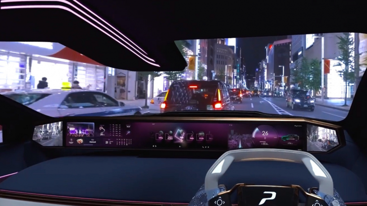
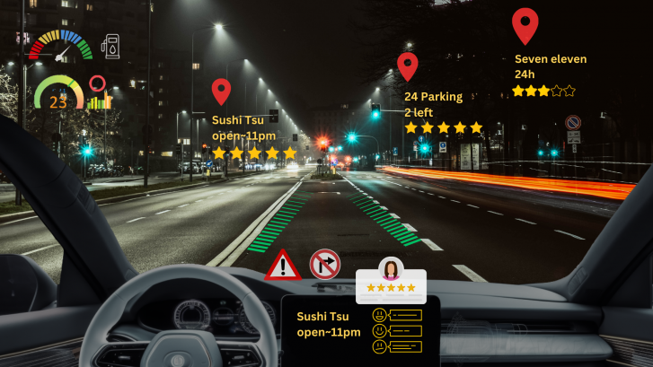
Going beyond a simple screen replacement, LPVIZ is an augmented reality driving assistance solution for the car. It allows displaying related content to a driver or passenger in 3D, superimposed to reality. Content can be placed anywhere inside the car, such as a virtual speedometer over the dashboard, and anywhere outside of the car, such as point-of-interest markers or navigation guidance.

The video on top of this post shows what a drive around the block in Azabujuban, Tokyo with LPVIZ looks like. A virtual dashboard is projected onto the center console of the vehicle. Arrows on the ground show lane guidance to the driver. Red Google Maps-style markers show points of interest. The virtual dashboard stays fixed to the same location in the car, even when the vehicle turns. The navigation arrows move smoothly and the point-of-interest markers are globally anchored.
Perfectly Tuned Components
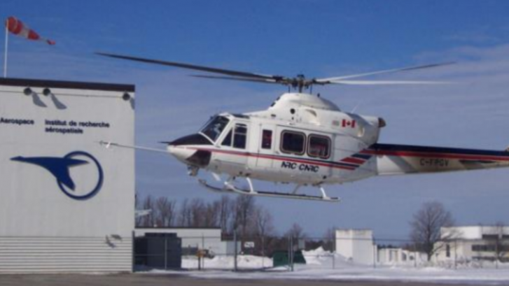
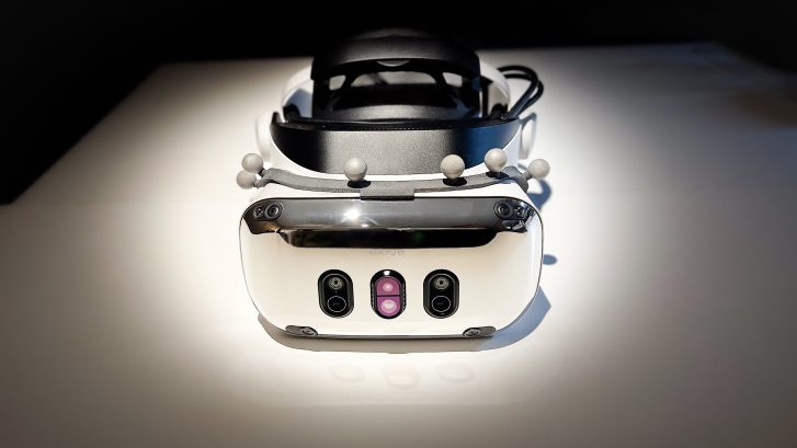
LPVIZ consists of several components that all have to interact perfectly to create a compelling and safe augmentation experience. The below illustration shows a block diagram of how the hardware components are connected.

Accurate tracking is required to display useful content to the driver: the HMD pose in the local car coordinate system and the vehicle pose in a globally anchored frame. Precise calibration of all components of the solution is essential to provide the highest visual fidelity and driver safety. Our LPVIZ product makes all parts of the system available in a compact form factor, ready to be integrated with any vehicle.


The Past, Present and the Future
In the current development stage we’re focusing on the most essential aspects of the solution: displaying a virtual dashboard, navigation information and points-of-interest. While this is our proprietary content, we’re opening our software to work with 3rd party developers to create their own content building on our platform.
Currently we’re offering LPVIZ as a B2B solution for prototyping, design and research. However, we’re working on reducing system complexity to make it work as a consumer facing automotive after-market solution to be released later this year.
Towards a Consumer Product
We are very proud of the progress our team has made in the past months. We’re moving closer to making our vision of an augmented reality driving assistance system a reality for everyone. One very important take-away from our recent developments is that it’s indeed possible to provide real utility to the driver using technology that is readily available. It might still be early days, but we’re edging towards a product that could appeal to a wider consumer market. This is just the beginning.