LPNAV – Outdoor Operation and 2D Map Building for Automatic Guided Vehicles (AGV)

LPNAV for Flexible, Rapid AGV Deployment

LPNAV enables automatic guided vehicles (AGV) to rapidly understand their environment and be ready for safe and efficient operation; no calibration, manual map building etc. is required.

With the help of LPNAV, mobile logistics platforms can operate (localize) in both, indoor and outdoor environments with the same set of sensors (Figure 1) and a unified map, e.g. when transporting an item from inside a warehouse to a truck parked in front of the warehouse. This offers a big cost-saving potential for applications in which so far the transition from indoor to outdoor settings required specialized equipment or manual handling.

Outdoor Localization

In a previous post we have shown the capability of LPNAV to operate in a small, crowded indoor environment. After further optimization of the algorithm we are now able to show the system working well in outdoor settings. Uncontrolled outdoor environments are particularly challenging as lighting conditions can vary very strongly and perception can be disturbed by pedestrians, passing cars etc.

In the video above we show the following capabilities of the system:

  • LPNAV is able to build a 3D map of its environment and localizes itself in real-time relative to its starting position.
  • Previously acquired map data can be used for localization. The map is automatically updated to environment changes.
  • When manually placed at a deliberate location on the map, an LPNAV-powered robot can instantly re-localize.
  • The system is robust to camera occlusions. Sensor fusion with IMU and odometry allows temporary operation without visual features.
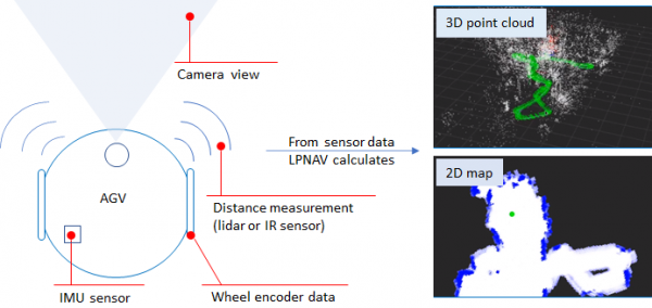
Figure 1 – LPNAV combines information from visual SLAM (camera), inertial measurement unit (IMU), distance sensors (lidar, IR) and wheel encoder data to calculate low-latency, high-accuracy localization results. The robot maps its environment to both, a 3D point cloud map and a human-readable 2D obstacle map.

2D Real-time Map Building

The 3D point-cloud maps built by LPNAV’s visual SLAM work well for computational localization of the robot inside its environment, but they are hard to intuitively understand by humans. Therefore we added a feature to LPNAV that allows building 2D maps of the robot environment based on information from its IR distance sensors. To achieve 2D wall / obstacle mapping at larger distances, alternatively to the IR sensors a 2D Lidar can be used.

The 2D real-time mapping capability is demonstrated in the video below:
LPNAV-VAC – Cost-Efficient Navigation System for AGVs

Introduction

We’re proud to announce a breakthrough result in the development of our LPNAV low-cost navigation system for small-sized automatic guided vehicles (AGV).

One focus area of LPNAV are vacuum cleaning robots that require spatial understanding of their environment to calculate an optimum cleaning strategy. As vacuum cleaning robots are mainly consumer devices, solutions for this market need to be cost-efficient, while maintaining state-of-the-art performance.

Figure 1 – The LPNAV-VAC development kit contains a robot platform, a dedicated computing unit, an IMU sensor and a camera

Development Platform

LPNAV-VAC combines three different data sources in order to calculate a robot’s position inside a room: an inertial measurement unit, data from the robot’s wheel encoders and video images from a camera installed on the robot (Figure 1). A central computing unit combines the information from these data sources to simultaneously create a map of the surroundings of the robot and calculate the position of the robot inside the room.

It is essential that sensor fusion algorithm is able to dynamically update the map it is constructing. As new sensor information arrives the map is continuously adapted to reflect an optimized view the robot’s environment.

While this principle of simultaneous localization and mapping (SLAM) is an established method for some robot navigation systems, these solutions tend to rely on laser scanners (LIDAR) or vision-only reconstruction. The combination of all available data sources in the robot allows LPNAV-VAC to create high definition maps of the environment while using low-cost, off-the-shelf components.

First Demonstration

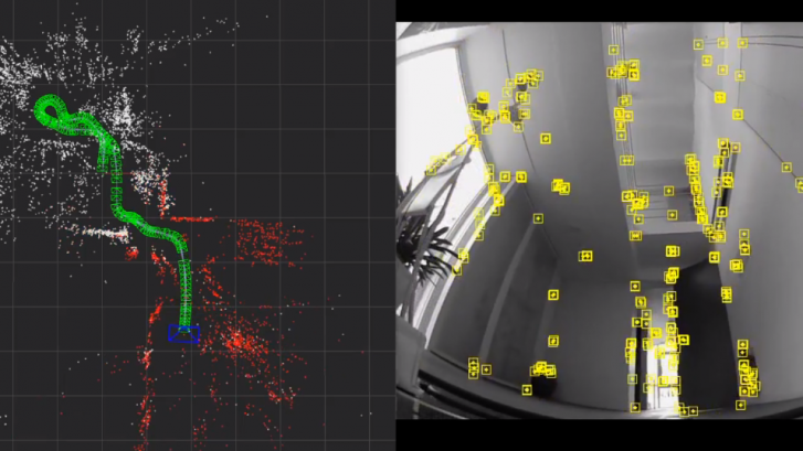
In the demonstration video above my colleague and main developer of LPNAV-VAC is steering our AGV platform through the ground floor of our Tokyo office. While the right side of the screen shows the view from the robot camera and detected visual features, the right side shows the path of the robot through the environment. As the robot progresses through the room a 3D map is created and continuously updated.

Please note that the robot doesn’t lose tracking during turns, while driving over small steps in the room or with changing environment lighting. Also Thomas moving around in front of the camera doesn’t disturb the LPNAV algorithm.

Using this map and the robot’s position information a path planning algorithm can find an optimum path for the robot to efficiently clean the room.

See-through Display First Look – LPVIZ (Part 3)

Virtual Dashboard Demonstration

This is a follow-up post to the introduction of our in-vehicle AR head mounted display LPVIZ part 1 and part 2.

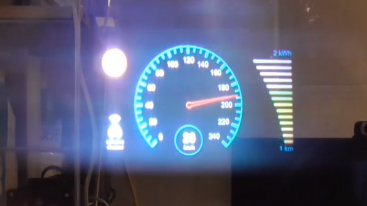
To test LPVIZ we created a simple demo scenario of an automotive virtual dashboard. We created a Unity scene with graphic elements commonly found on a vehicle dashboard. We animated these elements to make the scene look more realistic.

This setup is meant for static testing at our shop. For further experiments inside a moving vehicle we are planning to connect the animated elements directly to car data (speed etc.) communicated over the CAN bus.

The virtual dashboard is only a very simple example to show the basic functionality of LPVIZ. As described in a previous post, many a lot more sophisticated applications can be implemented.

The video above was taken through the right eye optical waveguide display of LPVIZ. We took this photo with a regular smartphone camera and therefore it is not very high quality. Nevertheless, it confirms that the display is working and correctly shows the virtual dashboard.

The user is looking at the object straight ahead. In case the user rotates his head or changes position, his view of the object will change perspectively. An important point to mention is the high luminosity of the display. We took this photo with the interior lighting in our shop turned on normally, and without any additional shade in front of the display.

Design Prototype and Inside-out Tracking – LPVIZ (Part 2)

LPVIZ Prototype Industrial Design

This post is a follow-up to the introduction of our augmented reality (AR) headset LPVIZ. See our previous post here.

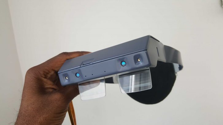
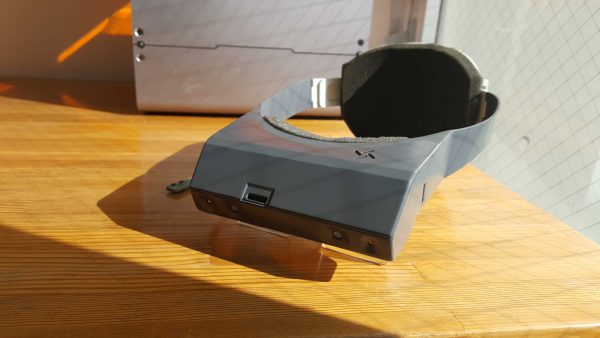
For the past two months the LPVIZ team has been working hard to improve our initial prototype. We have enhanced the device’s appearance and optimized it ergonomically. My colleague Seeon Mitchel has made draft 3D prints of the design that he has been planning for the initial release of LPVIZ. The results are looking excellent (Figure 1 & 2).

The ring design for fixing the unit to the user’s head feels comfortable. Even for longer usage duration the unit does not cause fatigue to the neck. See below two photos of the current functional prototype with the newly printed shell.

Figure 1, 2 – The fully functional LPVIZ design prototype

Inside-out Tracking and Gesture Recognition

The latest LPVIZ prototype features a built-in stereo camera. We are using the excellent Rigel module by the company UltraLeap that allows us to, at the same time, run a SLAM (simultaneous localization and mapping) algorithm and UltraLeap’s hand tracking.

Using the Rigel’s stereo camera, my colleague Thomas Hauth has developed a state-of-the-art inside-out tracking algorithm that allows the headset to be used inside a vehicle, even if no special cameras are installed. The video (Figure 3) below shows the fundamental functionality of the algorithm.

Figure 3 – The video shows the fundamental functionality of the LPSLAM inside-out tracking algorithm

It is important to note that this will not be a full replacement for ART outside-in tracking inside the vehicle. ART’s tracking engine is more accurate and robust under difficult lighting conditions. Still, our purpose is to also serve customers that have a smaller budget or no possibility to install additional equipment inside their vehicle.

Thomas wearing LPVIZ

AR HMD for In-Car Applications – LPVIZ (Part 1)

What is In-Vehicle AR

This article describes our first steps in the development of an AR HMD for in-car, aerospace and naval applications.

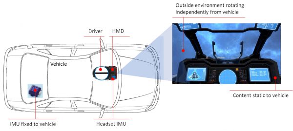
Over several years we have developed our LPVR middleware. In the first version the purpose of this middleware was to enable location-based VR with a combination of optical and IMU-based headset tracking. Building on this foundation we extended the system to work as a tracking solution for transportation platforms such as cars, ships or airplanes (Figure 1).

In contrast to stationary applications where an IMU is sufficient to track the rotations of an HMD, in the in-vehicle use-case, an additional IMU needs to be fixed to the vehicle and the information from this sensor needs to become part of the sensor fusion. We realized this with our LPVR-DUO tracking system.

Applying this middleware to existing augmented reality headsets on the market turned out to be challenging. Most AR HMDs use their own proprietary tracking technology that is only suitable for stationary use-cases, but doesn’t work in moving vehicles. Accessing such a tracking pipeline in order to extend it with our sensor fusion is usually not possible.

Illustration of In-car VR Installation

Figure 1 – Principle of in-car AR/VR as implemented with LPVR-DUO

Applications

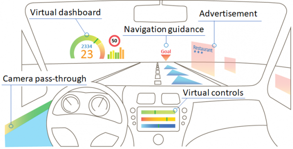
There are a large number of applications for in-car augmented reality ranging from B2B use-cases for design and development to consumer-facing scenarios. A few are listed in the illustration below (Figure 2).

AR applications in a car

Figure 2 – In-car AR use cases range from a simple virtual dashboard to interactive e-commerce applications. The “camera pass-through” enables the driver to virtually look through the car to see objects otherwise occluded by the car chassis.

HMD Specifications

For this reason, we decided to start the development of LPVIZ, an AR HMD dedicated to in-vehicle applications. This AR HMD for in-car, aerospace and naval applications is to represent the requirements of our customers as closely as possible:

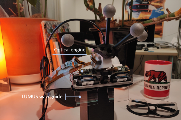
  • Strong optical engine with good FOV (LUMUS waveguides), unobstructed lateral vision (safety), low persistence and high refresh rate
  • System satisfies all requirements for immersive AR head tracking (pose prediction, head motion model, late latching, asynchronous timewarp etc.)
  • HMD is thethered to computing unit in vehicle by a thin VirtualLink cable
  • Computing unit is compact, but powerful enough to run SteamVR and thus supports a large range of software applications
  • Options to use either outside-in or inside-out optical tracking inside the vehicle, as well as LeapMotion hand tracking

In-Car HMD Hardware Prototype Development

We have recently created the first prototype of LPVIZ, with hardware development still in a very early stage, but enough to demonstrate our core functionality and use-case well.

Thomas wearing LPVIZ

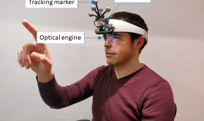
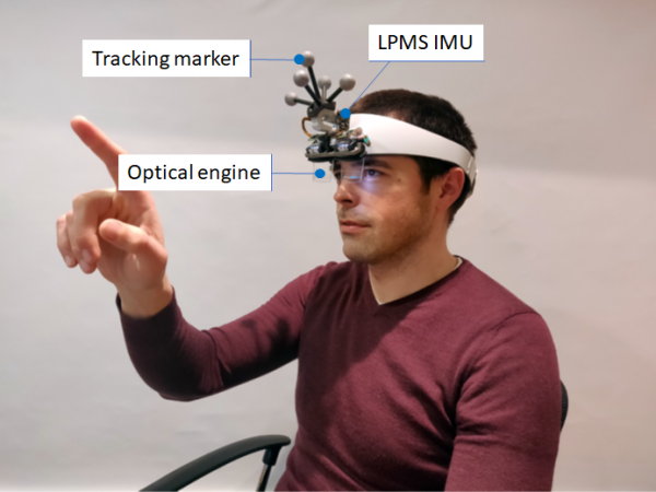
Figure 3 – Tracking of LPVIZ works based on our LPVR-DUO technology making use of ART outside-in tracking and our LPMS-CURS2 IMU module. This image shows Dr. Thomas Hauth performing an optical-see-through (OST) calibration.

Figure 4 – The LPVIZ prototype is powered by a LUMUS optical engine. This waveguide-based technology has excellent optical characteristics, perfectly suitable for our use-case.

Work in Progress

As you can see from the prototype images, our hardware system is still very much in an alpha stadium. Nevertheless we think it shows the capabilities of our technology very well and points in the right direction. In the next hardware version that will already be close to a release model, we will reduce the size of the device, applying the points below:

  • Use active marker LEDs instead of large passive marker balls OR inside-out tracking
  • Collect all electronics components on one compact electronics board, with only one VirtualLink connector
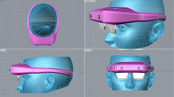
  • Create a compact housing, with a glasses-like fixture instead of a VR-style ring mount (Figure 5)

Figure 5 – First draft of a CAD design for the housing of the LPVIZ release version

1 2 3 4 5 7