Low-cost IMU Devices: High-Precision LPMS Next Gen
The new LPMS CURS2 sensor

The new LPMS CURS2 sensor


We proudly launched the next generation of our LPMS inertial measurement units developed for fast and accurate 3D orientation sensing. LP-RESEARCH supports a variety of communication interfaces and housing options at low cost. Let us tell you more about the optimized features:

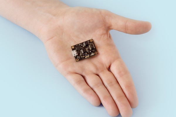
  • The new sensors are roughly half the size of the previous production, especially if you take a look at the new LPMS-B2.
  • Performance has been greatly increased in terms of accuracy. The noise level is now one third of the previous version.
  • Higher sampling rate: We were able to bring the sampling rate up to 400Hz.
  • The new sensors feature more types of data output, for example humidity.
  • Both LPMS-CANAL2 and LPMS-RS232AL2 are encased in a rugged aluminum housing and are waterproof up to 1m (IP67).
  • The first generation comprised seven sensors, now we increased the line to nine with greater variety.
  • Finally, thanks to a different manufacturing process, our new generation cost half or even less than half the price of the previous version.

Have a look at our LPMS product site over here.

IMU Distributor UK: LP-Research & Omni Instruments Ltd

IMU Distributor UK: LP-Research & Omni Instruments Ltd

We are happy to announce that we are starting a collaboration with Omni Instruments Ltd. in the UK. Omni Instruments Ltd. is developer and distributor of high definition measurement and logging systems. We have started the collaboration with offering two versions of the LPMS sensor system under the Omni Instruments brand. Please see the below links for further information:

LPMS-CU 9-Axis IMU AHRS Motion Sensor with CANbus and USB Connectivity
LPMS-B 9-Axis IMU AHRS Motion Sensor with Bluetooth Connectivity

OEM IMU Sensor Modules: LPMS-B & LPMS-CU Integration

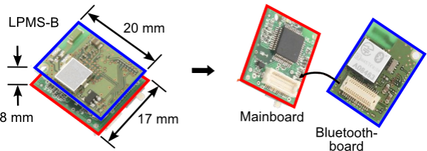
We also offer a so-called OEM version of our sensors. That means a bare bone version of the sensor without case and (in the case of LPMS-B) battery. We recommend buying a full development kit for testing of the sensor for first-time customers. However if you intend to integrate the sensor into your special design, the reduced space requirements of the OEM version might be very attractive.

Additionally to connectivity provided by the daughterboard, the LPMS-CU and LPMS-B mainboard can communicate by RS-232 (TTL levels). The RS-232 levels can be accessed through the SMD connector (as shown below) between sensor mainboard and communication daughterboard. Please contact us, if you need further information about this connector.

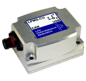
Rugged IMU Aluminium Case: LPMS-CU Housing Option

So far we have offered our customers only one packing option for the LPMS-CU, our standard blue plastic casing. The plastic case is small, very light and fairly robust. However, in harsh environments or in places that engineers regularly access with larger tools, we thought that a more rugged case for the LPMS-CU might be desireable. Therefore we have designed a new Aluminium casing option for LPMS-CU: the LPMS-CU-Rugged. Customers can from now on order this casing as an option when purchasing the LPMS-CU. The case is slightly larger and heavier than the plastic case, but made from 2mm Aluminium, it is almost indestructable.

Magnetic Field Calibration Data: Visualization & IMU Yaw

One of the trickiest things for reliably measuring orientations with the LPMS is the calibration of the magnetic field sensor. The functionality of the sensor is essential for determining the yaw angle of the sensor without drift. If we used only the gyrsocope to measure the yaw angle a drift of a few angles would already occur after 10 or 20 seconds of movement.

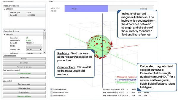
The normally spherical shape of the environment magnetic field is, especially in the vicinity of metal or electric circuits, often distorted to an ellipsoid. Such distoritions are efficiently compensated by calibrating the LPMS. However it is hard for the user to see if the calibration was successful or what the resulting data means about the surrounding electromagnetic field. Therefore we added a visualization of this data to the control software of the sensor (LpmsControl) that is to give a better understanding of the calibration results (see image below).

We use a special algorithm to reduce the influence of a distorted magnetic environment field on the orientation measurements of the sensor. A comparison of orientation tracking without and with using this algorithm is shown below.

1 4 5 6 7