Accurate Mixed Reality with LPVR-CAD and Varjo XR-3

Anchoring Virtual Objects with Varjo XR-3

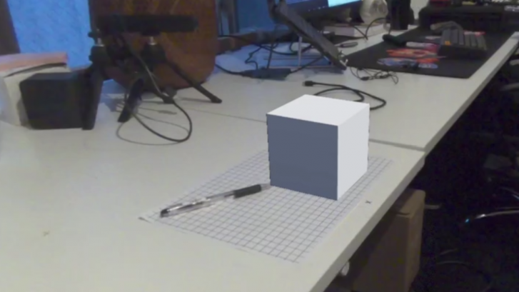
A key aspect of making a mixed reality experience compelling and useful is to correctly anchor virtual content to the real world. An object that’s fixed in its position and orientation (pose) relative to the real world should not change its pose as seen by the user when they’re moving around in the scene wearing the headset. Imagine a simple virtual cube positioned to be sitting on a real table. As the user walks around, this cube should remain in place, regardless from which perspective the user looks at it.

In more detail, correct anchoring of virtual objects to reality depends on the following points:

  1. In order to create correctly aligned content in a mixed reality experience, accurate knowledge of the user’s head pose is essential. We calculate the head pose using LPVR-CAD.
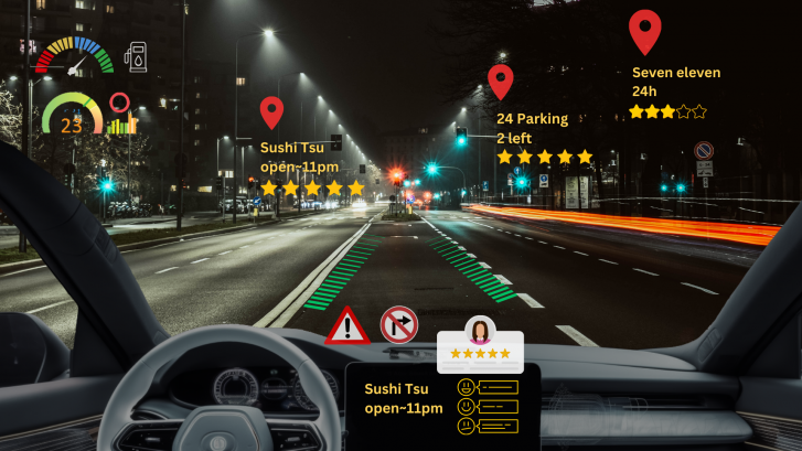
  2. The field of view provided by the cameras and the natural field of view of the human eyes are very different. Appropriate calibration is needed to compensate for this effect. The illustration below shows this inherent problem of video pass-through very clearly. Varjo’s HMDs are factory calibrated to minimize the impact of this effect on the user experience.

To get a better idea how a correct optical see-through (OST) calibration influences mixed reality performance we recommend playing with the camera configuration options in Varjo Lab Tools.

– Image credit: Varjo mixed reality documentation

Functional Testing of MR Performance

Our LPVR solution must at the very least achieve a precision that is satisfactory for our users’ typical applications. Therefore we decided to do a series of experiments to evaluate the precision of our system for mixed reality experiences and how it compares with SteamVR Lighthouse tracking.

We looked at the following configurations to make our evaluation:

# HMD Engine Tracking system Varjo markers
1 Varjo XR-3 Unreal 5.2 LPVR-CAD No
2 Varjo XR-3 Unreal 5.2 Lighthouse No
3 Varjo XR-3 Unreal 5.2 LPVR-CAD Yes
4 Varjo XR-3 Unreal 5.2 Lighthouse Yes

1 – LPVR Tracking without Varjo Markers

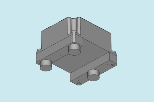
In this scenario we fixed a simple virtual cube on a table top in a defined position and orientation. The cube is the only virtual object in this scenario, everything else is the passed-through live video feed from the HMD cameras. We are tracking the HMD using LPVR-CAD in connection with an ART Smarttrack 3. No markers are used to stabilize the pose of the cube.

Important note: The tracking performance for the mixed reality use case can significantly change if the marker target that is attached to the HMD is not correctly adjusted. Please refer to the LPVR-CAD documentation or contact us for further support.

2 – Lighthouse Tracking without Varjo Markers

This scenario is in its basic setup identical to scenario #1, except that we’re using Lighthouse tracking to find the pose of the HMD.

3 – LPVR Tracking with Varjo Markers

Regardless how well the tracking of the HMD itself is working, as long as distortions of the environment as seen via the video pass-through feed aren’t perfectly compensated, there will be a discrepancy of where objects are displayed in reality and in virtual view space. As there are limits to the precision of such an optical see-through calibration (OST), another way to compensate for its effect is to get additional information about the environment directly from the video feed and align objects to it.

Such a tool are Varjo markers, ie. QR codes that are placed in the image. Using image analysis, virtual objects can be fixed to such QR codes and therefore automatically realigned to teh video feed as the user moves around. The video below shows the result of this scenario.

4 – Lighthouse Tracking with Varjo Markers

In our final test scenario we did the same experiment as in scenario 3, just with Lighthouse tracking instead of LPVR tracking.

Conclusion

See a table with our preliminary findings below:

Test Scenario LPVR Tracking Lighthouse Tracking
Without Varjo Markers 2 2.5
With Varjo Markers 1.5 1.5

– Approximate displacement error on horizontal plane (in cm)

Using the same room setup and test scene, the mixed reality accuracy of LPVR-CAD and Lighthouse tracking is similar. With both tracking systems slight shifts of 1-2cm depending on the head movement can be observed. A way to further reduce this residual drift is to use Varjo markers that further align virtual objects with the video feed from the pass-through cameras. Good results with LPVR tracking require precise adjustment of the optical target attached to the headset.

Note that our method of estimating the displacement error is rather qualitative than quantitative. With this post we made a general comparison of LPVR and Lighthouse tracking, with and without Varjo markers. A more quantitatively accurate evaluation will follow.

For customers wanting to reduce as much drift as possible, we recommenced the use of markers and optical tracking. There may be different results using Varjo XR-4 and other variations on the tracking environment or displayed content, which could warrant further testing in the future.

Immersive Driving Assistance with LPVIZ

How LPVIZ Augments Driving Reality

Going beyond a simple screen replacement, LPVIZ is an augmented reality driving assistance solution for the car. It allows displaying related content to a driver or passenger in 3D, superimposed to reality. Content can be placed anywhere inside the car, such as a virtual speedometer over the dashboard, and anywhere outside of the car, such as point-of-interest markers or navigation guidance.

The video on top of this post shows what a drive around the block in Azabujuban, Tokyo with LPVIZ looks like. A virtual dashboard is projected onto the center console of the vehicle. Arrows on the ground show lane guidance to the driver. Red Google Maps-style markers show points of interest. The virtual dashboard stays fixed to the same location in the car, even when the vehicle turns. The navigation arrows move smoothly and the point-of-interest markers are globally anchored.

Perfectly Tuned Components

LPVIZ consists of several components that all have to interact perfectly to create a compelling and safe augmentation experience. The below illustration shows a block diagram of how the hardware components are connected.

Accurate tracking is required to display useful content to the driver: the HMD pose in the local car coordinate system and the vehicle pose in a globally anchored frame. Precise calibration of all components of the solution is essential to provide the highest visual fidelity and driver safety. Our LPVIZ product makes all parts of the system available in a compact form factor, ready to be integrated with any vehicle.

The Past, Present and the Future

In the current development stage we’re focusing on the most essential aspects of the solution: displaying a virtual dashboard, navigation information and points-of-interest. While this is our proprietary content, we’re opening our software to work with 3rd party developers to create their own content building on our platform.

Currently we’re offering LPVIZ as a B2B solution for prototyping, design and research. However, we’re working on reducing system complexity to make it work as a consumer facing automotive after-market solution to be released later this year.

Towards a Consumer Product

We are very proud of the progress our team has made in the past months. We’re moving closer to making our vision of an augmented reality driving assistance system a reality for everyone. One very important take-away from our recent developments is that it’s indeed possible to provide real utility to the driver using technology that is readily available. It might still be early days, but we’re edging towards a product that could appeal to a wider consumer market. This is just the beginning.

LPVR-DUO in an Airborne Helicopter

In-Flight VR

Imagine soaring through the skies as a pilot, testing the limits of a helicopter’s capabilities while feeling the rush of wind and turbulence. Now imagine that you don’t see the real world outside and the safe landing pad that your helicopter is approaching but a virtual reality (VR) scene where you are homing in on a ship in high seas. The National Research Council Canada (NRC) and Defence Research and Development Canada (DRDC) have brought this experience to life with their groundbreaking Integrated Reality In-Flight Simulation (IRIS).

IRIS is not your ordinary simulator; for one, it’s not sitting on a hexapod, it’s airborne. It’s a variable-stability helicopter based on the Bell 412 that can behave like other aircraft and can simulate varying weather conditions; combine that with a VR environment and you have a tool that allows safely training operations in the most adverse conditions. In particular it is used for Ship Helicopter Operating Limitations (SHOL) testing.

Mission-Critical Application with LPVR-DUO

The LPVR-DUO system is what makes VR possible on this constantly moving platform. This cutting-edge AR/VR tracking system seamlessly merges the inertial measurements taken by the headset with the helicopter’s motion data and a camera system mounted inside the cabin to provide the correct visuals to the pilot. The challenges of using cameras to track the VR headset inside the tight environment of the helicopter while lighting conditions are ever-changing are overcome by using an ART SmartTrack 3 system. This system follows an arrangement of reflective markers attached to the pilot’s helmet. The VR headset is attached to the helmet in such a way that the pilot can wear it as if it were a pair of night vision goggles. Put together, this allows displaying a virtual world to the pilot, even in the most extreme maneuvers.

To ensure an authentic experience, the IRIS system incorporates real-time turbulence models, meticulously crafted from wind tunnel trials. These turbulence effects are seamlessly integrated into the aircraft’s motion and into the VR scene, providing pilots with precise proprioceptive and vestibular cues. It’s a symphony of technology and innovation in the world of aviation testing.

In-Cockpit Implementation

The optical tracking system relies on highly reflective marker targets on the helmet to track movement in three dimensions. Initially, only five markers were installed, strategically placed for optimal tracking. But the pursuit of perfection led NRC to create custom 3D-printed low-reflectivity helmet molds, allowing them to mount a dozen small passive markers. This significantly improved tracking reliability in various lighting conditions and allowed for a wider range of head movement.

Recently, NRC put this remarkable concept to the test with actual flight trials. The response from pilots was nothing short of exhilarating. They found the system required minimal adaptation, exhibited no noticeable lag, and, perhaps most impressively, didn’t induce any motion sickness. Even the turbulence effects felt incredibly realistic. Surprisingly, the typical VR drawbacks, such as resolution and field of view limitations, had minimal impact, especially during close-in shipboard operations. It’s safe to say that IRIS has set a new standard for effective and immersive aviation testing.

Publication of Results

The NRC team presented their results at the Vertical Flight Society’s 79th Annual Form in two papers [1] and [2] and they also have a blog post on their site.

NOTE: Image contents courtesy of Aerospace Research Centre, National Research Council of Canada (NRC) – Ottawa, ON, Canada

High-performance Use Cases of LPVR & Varjo Headsets

Components of a VR/AR Operating System

Augmented and virtual reality technology helps boost worker productivity in various fields such as automotive, aerospace, industrial production, and more. Whereas the context of these applications is usually fairly specific, some aspects are common to many of these use cases. In this article, we will specifically explore the topic of pose tracking of Varjo head mounted displays (HMDs) based on LP-RESEARCH’s LPVR operating system. We will further on show two customer use cases that utilize LPVR in different ways.

In a typical VR/AR setup, you find three main subsystems as shown in the illustration below:

With our LPVR operating system, we connect these three building blocks of an VR/AR system and make them communicate seamlessly with each other while providing a simple, unified interface to the user. Depending on the specific use case, users might select different types of hardware to build their VR/AR setup. Therefore LPVR offers a wide range of interface options to adapt to systems from various manufacturers.

LPVR Flavors

LPVR operates in different flavors, we can group end applications into two categories:

  • LPVR-CAD – Static AR/VR setups, where multiple users operate and collaborate in one or more joint tracking volumes. These tracking volumes can be situated in different locations.
  • LPVR-DUO – AR/VR systems that are located in a vehicle or on a motion platform: such systems have special requirements, especially on the tracking side. If, for example, you would want to track a headset inside a car, displaying a virtual cockpit anchored to the car frame, and a virtual outside world fixed to a global coordinate system, means of locating the car in the world and referencing the HMD locally in the car frame are required.


In the following paragraphs, we will introduce two customer use cases that cover these two basic scenarios.

Large-scale Industrial Design at Hyundai

– Varjo XR-3 at Hyundai Design Center with optical markers attached. Image credit: Hyundai

For the Korean automotive company Hyundai Motor Company, we created a large, location-based virtual reality installation at their research and development center in Namyang, Korea. The system is used to showcase, amend and modify prototype and production-ready automobile designs.

This application uses optical outside-in tracking and LP-RESEARCH’s LPVR-CAD solution to track up to 20 users wearing head-mounted displays. While LPVR allows a mix of different headset types to operate in the same tracking volume, the Varjo XR-3 gives the most outstanding performance to inspect objects in high resolution and great detail. Additionally to an HMD, users carry hand controllers for a total of more than 40 tracked objects in a space close to 400 sqm.

– Hyundai’s collaborative virtual reality design experience. Image credit: Hyundai

Responsiveness is achieved by using LPVR-CAD to combine data from the inertial measurement unit built into the headsets and information from the optical tracking system. The optical system uses 36 infrared cameras to track the 160 markers attached to the HMDs and hand controllers. Perfectly smooth and uninterrupted position and orientation data of each user’s HMD is achieved by using LP-RESEARCH’s sensor fusion algorithms.

Depending on the type of headset, users either wear a backpack PC, connect to a host wirelessly or use an extra-long cable to connect directly to a rendering PC outside the tracking volume.

“Currently, we are actively utilizing VR from the initial development stage to the point of development. In the future, we plan to increase accessibility and usability by simplifying equipment using wireless HMDs. For this, improving the speed and stability of wireless internet is essential, which we plan to address by introducing 5G. In addition, LP RESEARCH’s technology is essential for multi-user location sharing within a virtual space.” – SungMook Kang, Visualization Specialist, Hyundai Motor Company

Next-level Automotive Entertainment with CUPRA

Imagine.. playing Mario cart, your hands are gripping the wheel, and you are in Neo Tokyo, on a race track. Futuristic buildings keep flying by while you race ahead, drifting into long turns and leaving your competitors behind you.

Now imagine you are no longer in your living room, you are sitting in an actual race car, buzzing around in an empty parking lot. Instead of looking through the windshield with your own eyes, you are wearing a Varjo XR-3 HMD. What you see outside the car is a virtual world, it’s Neo Tokyo.

– The view through the Varjo XR-3 headset. Image credit: CUPRA

As the car moves on the parking lot, you move inside the virtual world. When you move your head inside the car’s cockpit, the motions of your head are accurately tracked.

– Varjo XR-3 inside the cabin of the Urban Rebel. Image credit: Fonk Magazine

– Cupra’s Urban Rebel drifting on the test course

Together with the Norwegian company Breach VR, we have implemented this experience for the automotive company CUPRA. CUPRA is relentlessly pushing the technology of their vehicles into the future, striving to provide a novel driving experience to their customers.

Tracking of the vehicle and the Varjo XR-3 inside the vehicle is achieved with LP-RESEARCH’s automotive tracking systems LPVR-DUO. As the headset’s gyroscope sensors record the superimposed motion data of the car and the user inside the car, a specialized sensing system, and the algorithm are required to separate the two.

The result of this cascade of exceptional technology is a compellingly immersive driving experience of the future. The combination of an outstanding visualization device like the Varjo XR-3, LPVR state-of-the-art tracking, BreachVR’s 3D software and design and, last but not least, the incredible CUPRA race cars make for an exciting ride that you’ll greatly enjoy and never forget. Come and join the ride!

Check this blog blog post in the Varjo Insider Blog.

Check out our Instagram for further use cases with Varjo’s HMDs: @lpresearchinc

コネクシオ 設備監視IoTシステムについて

概要

今回はコネクシオ様によって開発された工場等における設備監視IoTシステムについてご紹介します。本システムは工場設備の異常振動等を検知・モニタリングすることで故障予測や設備状況の把握することを目的としています。
振動を検知するために弊社の製品LPMS-IG1が使用されています。


使用事例:排水処理施設設備の監視

K社では廃水処理プラント施設を運用しています。本施設では有機性の浮遊物や油分が大量に含まれるビルピット汚泥など処理しづらい廃水を「メタン発酵処理」「活性汚泥処理」方法等を組み合わせたシステムにより物理的、生物化学的に分解処理を行っています。

問題

排水処理プラントは365日24時間稼働し続ける必要あります。
また、微生物の働きによって分解を行うため、設備を停止することはできません。そのような状況下において、深夜・早朝休祝日関わらず発生する突発的な故障や緊急対応の業務負荷が大きな課題となっています。

解決

コネクシオ様IoT設備監視システムを実験的に導入。
連続データの見える化により、人的監視では困難な解析や包括的な状態把握が可能となりました。遠隔からポンプの動作状況が確認でき稼働率、時系列での状態変化の把握が可能になった他、現場に行かなくても状態を確認できるため、保守点検・巡回業務の稼働が軽減しました。


実際の機器の写真(※1)


システム構成図(※1)


本システムの詳しい情報については下記のリンクをご参照下さい。

詳細はこちら


本システムにおけるLPMS-IG1

センサーフュージョン機能を搭載した MEMS9 軸 IMU「LPMS-IG1」は弊社製品の中でも最高精度のセンサとなっています。低ノイズ/低ドリフト (4℃/h) の加速度センサに加え、2 種類のジャイロセンサを搭載することにより、幅広い範囲での計測( 400 2000 °/s)が可能です。詳細は製品紹介ページ(日本語)をご確認下さい。

詳細はこちら

耐衝撃性+防水

LPMS-IG1は10,000Gの衝撃を耐える耐久性、IP67の防水機能を有しています。排水プラントのような水に関わる用途や、強い衝撃・振動が発生するケースでも問題なく使用することが可能です。


高いカスタマイズ性

今回のようなケースでは振動検知の精度が求められます。より幅広い数値範囲での振動を検知するため、ローパスフィルタのしきい値設定を変更。故障の予兆となりうる比較的小さな振動も検知できるようになりました。LPMS-IG1は設定ファイルを変更することで簡単にセンサのパラメータを変更することができます。


顧客の問題を解決

LP-Researchのサービスはセンサを販売して終わるわけではありません。
開発を進めていく中でセンサにまつわる様々な問題・不明点等が発生します。弊社ではお客様の問題を解決すべく全力でサポートしております。今回のコネクシオ様の開発においては開発に関する問い合わせ対応はもちろん、システムに必要となったパーツも弊社で開発しました。

開発したパーツ1:複数センサを接続できるCANケーブル


開発したパーツ2:センサをパイプに設置するためのアタッチメント


※1 出典:廃棄物処理施設でのモーター故障検知(K社様)

1 2 3 5