Design of an Efficient CAN-Bus Network with LPMS-IG1

Introduction to Designing an Efficient CAN-Bus Network

This article describes how to design an efficient high speed CAN-bus network with LPMS-IG1. We offer several sensor types with a CAN bus connection. The CAN bus is a popular network standard for applications like automotive, aerospace and industrial automation where connecting a large number of sensor and actuation units with a limited amount of cabling is required.

While creating a CAN bus network is not difficult by itself, there are a few key aspects that an engineer should follow in order to achieve optimum performance.

Efficient CAN-Bus Network Topology

A common mistake when designing a CAN bus network is to use a star topology to connect devices to each other. In this topology the signal from each device is routed to a center piece by connections of similar length. The center piece is connected to the host to acquire and distribute data to the devices of the network.
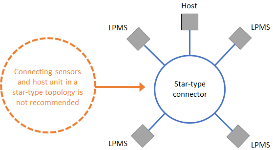
For reaching the full performance of a CAN bus network, we strongly discourage using this topology. Most CAN bus setups designed in this way will fail to work reliably and at high speed.

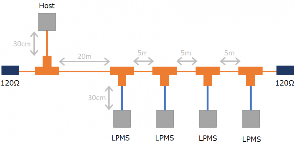
The CAN bus standard’s fundamental concept is to work best in a daisy chain configuration, with one sensor unit or the data acquisition host being the first device in the chain and one device being the last in the network.
Maximum CAN-Bus Speed and Cable Length

A key aspect for the design of an efficient high speed CAN-bus network is to correctly adjust bus cable lengths. The bus line running past each device is to be the longest connection in the network. Each sensor needs to be connected to the bus by a short stub connection. A typical length for such a stub connection is 10-30cm, whereas the main bus line can have a length of hundreds of meters, depending on the desired transmission speed.

Speed in bit/s Maximum Cable Length
1 Mbit/s 20 m
800 kbit/s 40 m
500 kbit/s 100 m
250 kbit/s 250 m
125 kbit/s 500 m

Note that a CAN bus network needs to be terminated using a 120 Ohm resistor at each end. This is especially important for bus length of more than 1-2m and should be considered as general good practice.

LPMS-IG1 CAN-Bus Configuration

One of our products with a CAN bus interface option is our LPMS-IG1 high performance inertial measurement unit. LPMS-IG1 can be flexibly configured to satisfy user requirements. It has the ability to output data using the CANopen standard, freely configurable sequential streaming or our proprietary binary format LP-BUS. These and further parameters can be set via our IG1-Control data acquisition application.
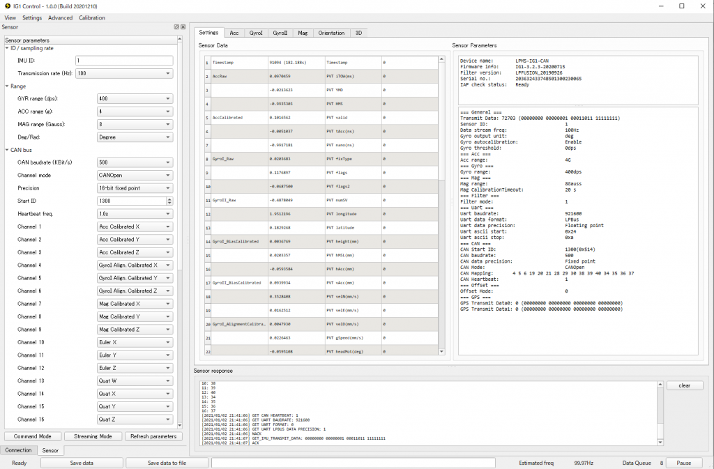
Some CAN bus data loggers that rely on the CANopen standard require users to provide an EDS file to automatically configure each device on the network. While we don’t support the automatic generation of EDS files from our data acquisition applications, depending on the settings in IG1-Control or LPMS-Control, it is possible to manually create an EDS file as described in this tutorial.

In this article we give a few essential insights into how to design an efficient high speed CAN-bus network with LPMS-IG1. If you would like to know more about this topic or have any questions, let us know!

Collaboration with Pimax

We are happy to announce a collaboration with the head-mounted display (HMD) manufacturer Pimax. Pimax HMDs feature very high resolution (up to 8K pixels) displays and an industry-leading field-of-view (max. 200°). By default, Pimax HMDs support SteamVR tracking and therefore are limited to relatively small tracking volumes.

We developed a special driver that allows our LPVR middleware LPVR-CAD and LPVR-DUO to work with Pimax headsets. Using LPVR, the headsets can now be used within a large-scale, location-based context, in connection with outside-in optical systems such as ART (Advanced Real-Time Tracking).

As Pimax is planning to implement UltraLeap hand tracking in their HMDs in the future, we are confident that we will also be able to extend our inside-out tracking algorithm to their devices.

The video above shows the basic functionality of tracking a Pimax HMD using LPVR and an optical tracking system. The headset’s motions are represented in SteamVR. For this demonstration the tracking volume is relatively small, but can be extended easily by using more outside-in tracking cameras.

This video was kindly provided to us by evoTec Solutions. Evotec is a new company in Switzerland that focuses on virtual reality (VR) solutions for corporations. Contact them for further information!

Big in Korea

Location-based Virtual Reality for Automotive Design

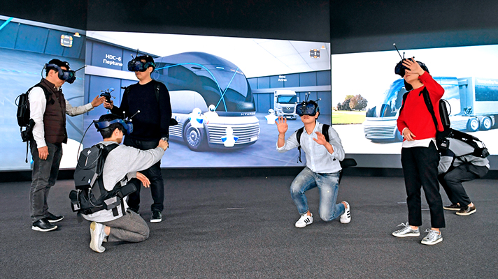
Figure 1 – Using LPVR-CAD large room-scale tracking, 3D design content is visualized on VIVE Pro HMDs

In cooperation with Korean automotive design solutions provider AP-Solutions, we created a large location based virtual reality installation at the Hyundai research and development center close to Seoul, Korea. The system is used to showcase, amend and modify prototype and production-ready automobile designs (Figure 1).

LPVR Large Room Scale Tracking Engine

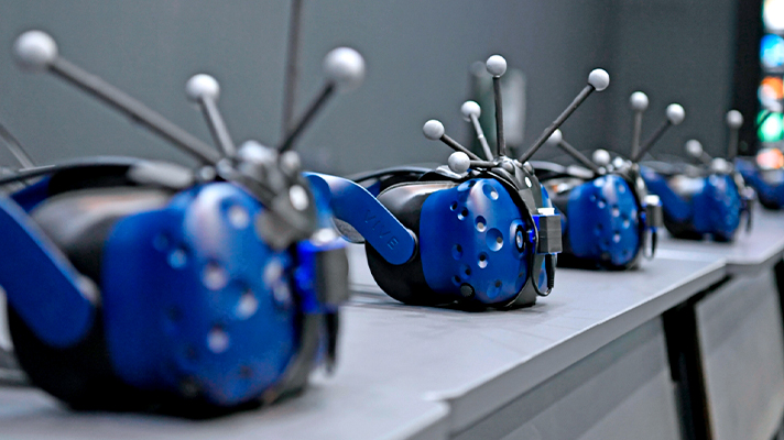
Figure 2 – Each VIVE Pro HMD is equipped with optical tracking markers and an LPMS-CU2 IMU. The IMUs are covered with black tape to avoid reflections of infrared light.

The system uses optical tracking together with LP-Research’s LPVR solution to track up to 20 users wearing Vive Pro Head-mounted Displays (HMD). Each user carries a VIVE hand controller for a total of 40 tracked objects in a space close to 400sqm.

Responsiveness is achieved by using LPVR (Figure 2) to combine LPMS IMU data and a software package to achieve optimum performance. The optical system uses 36 infrared cameras to track the 160 markers attached to the HMDs and hand controllers. The position and orientation data of each user’s HMD is combined using LP-Research’s algorithm.

The content of the virtual space is rendered using a CAD software package running on backpack PCs worn by each of the 20 users. The PCs communicate and coordinate via a central server.

Korean News Coverage

Images courtesy of Hyundai Motor Group Newsroom.

AVGVST Guest Post: Refining Human Motion

This is a guest post by AVGVST creative agency. AVGVST are our good neighbours here in Nishizabu Tokyo, so we thought it is a good idea to ask them to create a few good-looking blog posts for us.

Human Motion Capture

Human motion capture is a term commonly known from the world of movie production: Gollum in The Lord of the Rings lurking and smiling at his shiny ring in a weirdly human-like manner or the beautifully alien creatures of Avatar floating through a fantastic landscape.

Although transferring human body movements to a movie character is an established method, it might be surprising to some that human motion capture has a range of applications in a areas beyond the world of film production.

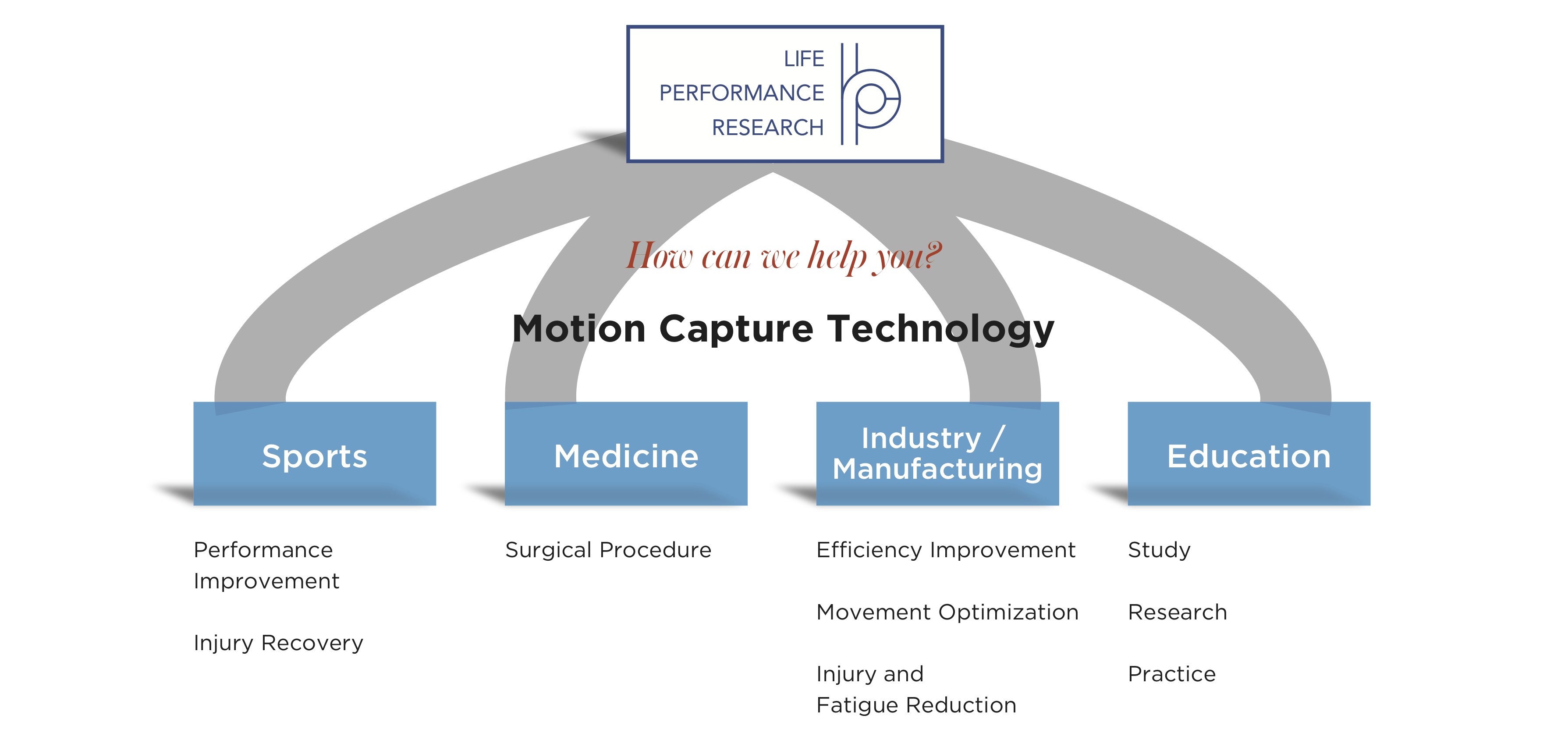
Motion Capture can improve human life by boosting a person’s work efficiency, support injury recovery and help preventing excessive strain on the human body under rough working conditions. The medical and manufacturing industries are just two of many fields where motion capture helps to optimizing human movements.

IMU-Based Technology for Refining Human Motion

One of the main topics of LP-RESEARCH for the application of its advanced sensor technology is to provide means for quantitatively refining human motion and make them faster, safer and more efficient.

LP-RESEARCH’s chief scientist Tobias Schlüter is writing software that uses motion sensor data to measure the movements of a person. Small sensors attached to the subject’s limbs track body motion and based on the acquired information, adjustments can be made to the subject’s movements.

This can result in improved speed safety and efficiency for a specific activity.

Motion capture AVGVST illustration

Worker Safety & Well-Being First in Industrial Production

Using this technology a patient trying to recover from a severe injury might find a faster way back to normal life. A runner working to improve his running style might gather useful information to optimize his training strategy.

A central topic in industrial manufacturing is the improvement of production efficiency: human workers performing repetitive tasks face problems of fatigue and physical conditions like back pain. Human motion capture and the corresponding analysis methods help to correct sub-optimal movements to help the work fatigue less, stay healthy and at the same time become more efficient.

With applications in sports, medical treatment, industrial production and more: Sensor technology from Tokyo – welcome to LP-RESEARCH.

To find out more details of how this technology works, please contact us

IMUcore Sensor Fusion

Introducing IMUcore

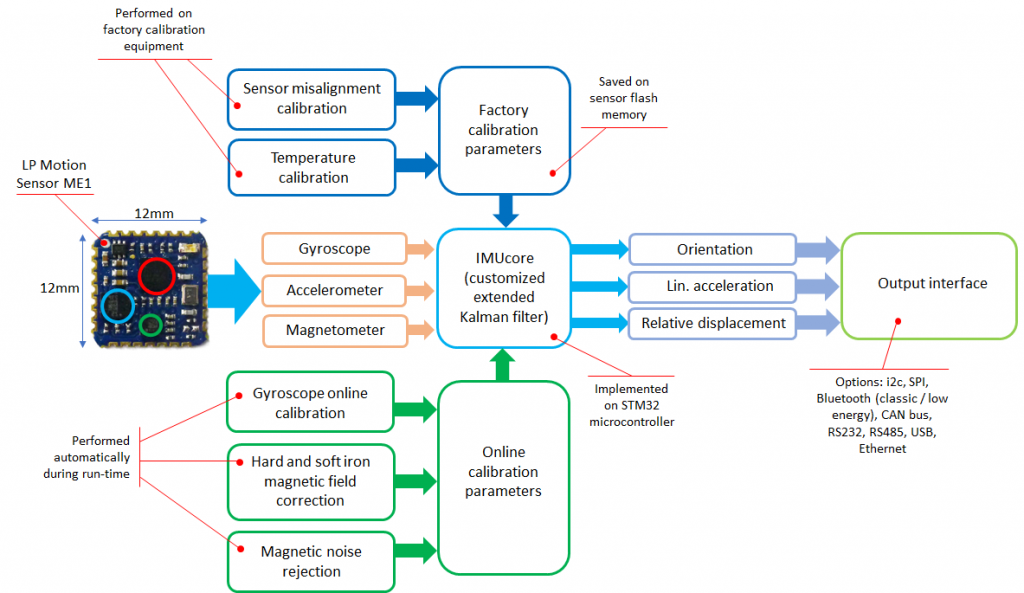
IMUcore is the central algorithm working inside all LP-RESEARCH IMUs. It collects orientation data from several sources and combines them into fast and drift-free tilt and direction information. To work with any type of MEMS sensor, various online and offline calibration methods have been implemented to guarantee high quality data output. The algorithm is very versatile and performance-saving. It can be implemented on embedded MCUs with minimum power consumption.

IMUcore is now available as a solution from LP-RESEARCH. Please contact us here for more information or a price quotation.

Overview of embedded sensor fusion in LPMS devices

Sensor Fusion Filter Overview

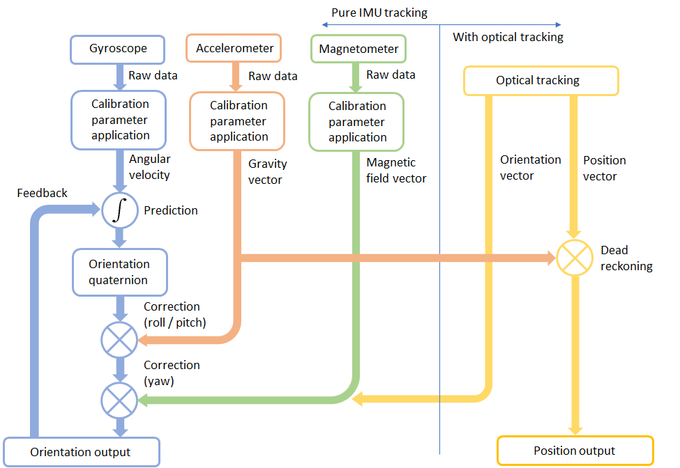
IMUcore uses gyroscope data as basis information to calculate orientation. Errors introduced through measurement noise are corrected by accelerometer and compass data. Optionally the sensor fusion can be extended with an optical (or other) tracking system to additionally provide position information.

All aspects of the IMUcore algorithm in one image

If this topic sounds familiar to you and you are looking for a solution to a related problem, contact us for further discussion.

1 2 3 4 5