
コネクシオ 設備監視IoTシステムについて
概要
今回はコネクシオ様によって開発された工場等における設備監視IoTシステムについてご紹介します。本システムは工場設備の異常振動等を検知・モニタリングすることで故障予測や設備状況の把握することを目的としています。
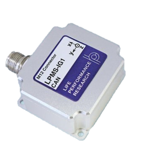
振動を検知するために弊社の製品LPMS-IG1が使用されています。
使用事例:排水処理施設設備の監視
K社では廃水処理プラント施設を運用しています。本施設では有機性の浮遊物や油分が大量に含まれるビルピット汚泥など処理しづらい廃水を「メタン発酵処理」「活性汚泥処理」方法等を組み合わせたシステムにより物理的、生物化学的に分解処理を行っています。
問題
排水処理プラントは365日24時間稼働し続ける必要あります。
また、微生物の働きによって分解を行うため、設備を停止することはできません。そのような状況下において、深夜・早朝休祝日関わらず発生する突発的な故障や緊急対応の業務負荷が大きな課題となっています。
解決
コネクシオ様と協力し、IoT設備監視システムを実験的に導入。
連続データの見える化により、人的監視では困難な解析や包括的な状態把握が可能となりました。遠隔からポンプの動作状況が確認でき稼働率、時系列での状態変化の把握が可能になった他、現場に行かなくても状態を確認できるため、保守点検・巡回業務の稼働が軽減しました。
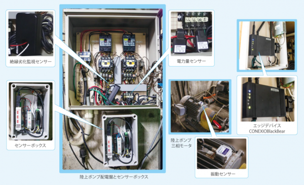
実際の機器の写真(※1)
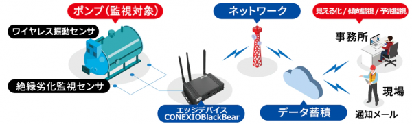
システム構成図(※1)
本システムにおけるLPMS-IG1
センサーフュージョン機能を搭載した MEMS9 軸 IMU「LPMS-IG1」は弊社製品の中でも最高精度のセンサとなっています。低ノイズ/低ドリフト (4℃/h) の加速度センサに加え、2 種類のジャイロセンサを搭載することにより、幅広い範囲での計測( 400 2000 °/s)が可能です。詳細は製品紹介ページ(日本語)をご確認下さい。
耐衝撃性+防水
LPMS-IG1は10,000Gの衝撃を耐える耐久性、IP67の防水機能を有しています。排水プラントのような水に関わる用途や、強い衝撃・振動が発生するケースでも問題なく使用することが可能です。
高いカスタマイズ性
今回のようなケースでは振動検知の精度が求められます。より幅広い数値範囲での振動を検知するため、ローパスフィルタのしきい値設定を変更。故障の予兆となりうる比較的小さな振動も検知できるようになりました。LPMS-IG1は設定ファイルを変更することで簡単にセンサのパラメータを変更することができます。
顧客の問題を解決
LP-Researchのサービスはセンサを販売して終わるわけではありません。
開発を進めていく中でセンサにまつわる様々な問題・不明点等が発生します。弊社ではお客様の問題を解決すべく全力でサポートしております。今回のコネクシオ様の開発においては開発に関する問い合わせ対応はもちろん、システムに必要となったパーツも弊社で開発しました。
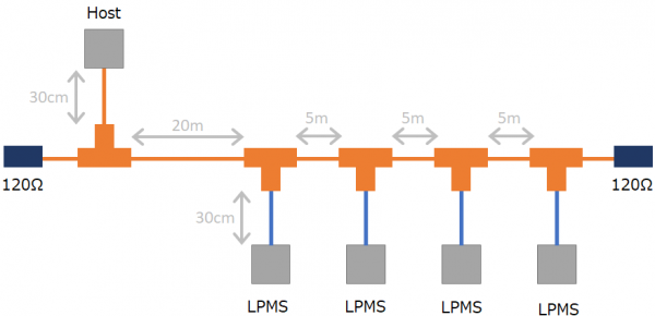
開発したパーツ1:複数センサを接続できるCANケーブル
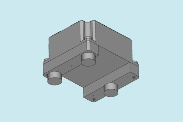
開発したパーツ2:センサをパイプに設置するためのアタッチメント
※1 出典:廃棄物処理施設でのモーター故障検知(K社様)


