Revolutionizing AD/ADAS Testing: VR-Enhanced Vehicle-in-the-Loop

The automotive industry is in a race to develop smarter, safer, and more efficient vehicles. To meet these demands, engineers rely on sophisticated development processes. At LP-RESEARCH, we’re committed to creating tools that shape the future of mobility. That’s why we’re excited to announce a groundbreaking collaboration with IPG Automotive.

By integrating our advanced hardware and software with IPG Automotive’s CarMaker, we’ve created an immersive Virtual Reality (VR) experience for Vehicle-in-the-Loop (ViL) testing. This powerful solution allows engineers to test Autonomous Driving and Advanced Driver-Assistance Systems (AD/ADAS) on a proving ground with unprecedented realism and efficiency.

What is Vehicle-in-the-Loop (ViL)?

Vehicle-in-the-Loop is a powerful testing method that blends real-world driving with virtual simulation. An AD/ADAS-equipped vehicle drives on a physical test track while interacting with a dynamic virtual environment in real time.

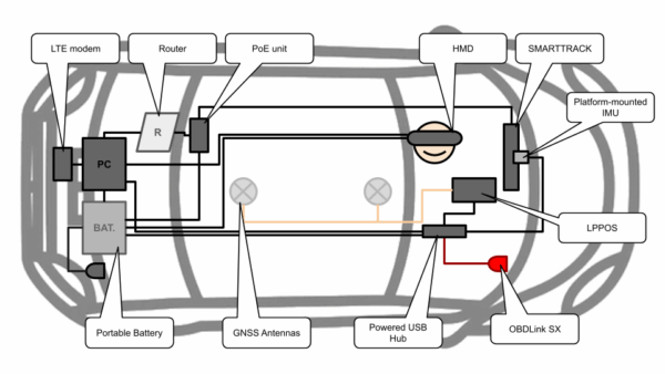
This approach lets engineers observe the vehicle’s response to countless simulated scenarios under controlled, repeatable conditions. The vehicle’s real-world dynamics are continuously fed back into the simulation, ensuring the virtual world perfectly mirrors the physical state of the car. The test vehicle is outfitted with a seamless integration of hardware and software to support this constant flow of data.

The Technology Stack: A Powerful Combination

Our collaboration combines best-in-class hardware and software from both LP-RESEARCH and IPG Automotive to deliver a complete ViL solution.

LP-RESEARCH Stack

LPPOS: Our hardware system for acquiring physical data from the vehicle via ELM327 or OBDLink, completed by Global Navigation Satellite System (GNSS) antennas, and advanced Inertial Measurement Units (IMUs). LPPOS includes FusionHub, our sensor-fusion software for high-precision, real-time vehicle state estimation. More information here

LPVR-DUO: Specialized sensor-fusion software that calculates the Head-Mounted Display (HMD) pose relative to the moving vehicle. More information here

ART SMARTRACK3: An advanced Infrared (IR) camera tracking system from our partner, Advance Realtime Tracking (ART), for precise head tracking.

IPG Automotive Stack

CarMaker Office: The simulation environment, enabled with the ViL add-on.

Movie NX: The visualization tool, enhanced with the VR add-on to create the immersive experience.
How It All Works Together

The key to this integration is a custom plugin that connects out FusionHub software with CarMaker. This plugin translates the real vehicle’s precise position and orientation (it’s “pose“) into the virtual environment.

The system workflow is a seamless loop of data capture, processing, and visualization:

Data Acquisition: LPPOS gathers vehicle data (OBD), GNSS, and IMU measurements and sends it to FusionHub. The SMARTRACK system monitors the HMD’s position, while IMUs on the headset and vehicle platform send orientation data to LPVR-DUO.

Sensor Fusion: FusionHub processes its inputs to calculate the vehicle’s exact pose in the real world. LPVR-DUO calculates the HMD’s pose relative to the moving vehicle’s interior.

Real-Time Communication: FusionHub streams the vehicle’s pose to a dedicated TCP server, which feeds the data directly into the CarMaker simulation via our custom plugin. LPVR-DUO communicates the headset’s pose to Movie NX using OpenVR, allowing the driver or engineer to naturally look around the virtual scene from inside the real car.

The entire LP-RESEARCH software stack and CarMaker Office run concurrently on a single computer inside the test vehicle, creating a compact and powerful setup.

See It in Action

We configured a scene in the CarMaker Scenario Editor that meticulously replicates our test track near the LP-RESEARCH Tokyo Office. The video on the top of this post demonstrates the fully integrated system, showcasing how the vehicle’s real-world position perfectly matches its virtual counterpart. Notice how the VR perspective shifts smoothly as the copilot moves their head inside the vehicle.

This setup vividly illustrates how VR technology makes ViL testing more immersive, effective, and even fun.

Advance Your ViL Testing Today

Are you ready to integrate cutting-edge virtual reality into your Vehicle-in-the-Loop testing and help shape the future of mobility?

Fine-tuning the HMD view and virtual vehicle reference frame is crucial for an accurate simulation and depends on the specific test vehicle and scenario. Our team has the expertise to configure these parameters for you or provide expert guidance to ensure a perfect setup.

Contact us today to learn how our tailored solutions and expert support can elevate your AD/ADAS development process.

Introducing LP-Research’s SLAM System with Full Fusion for Next-Gen AR/VR Tracking

At LP-Research, we have been pushing the boundaries of spatial tracking with our latest developments in Visual SLAM (Simultaneous Localization and Mapping) and sensor fusion technologies. Our new SLAM system, combined with what we call “Full Fusion,” is designed to deliver highly stable and accurate 6DoF tracking for robotics, augmented and virtual reality applications.

System Setup

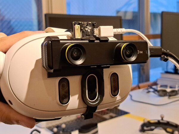
To demonstrate the progress of our development, we ran LPSLAM together with FusionHub on a host computer and forwarded the resulting pose to a Meta Quest 3 mixed reality headset for visualization using LPVR-AIR. We created a custom 3D-printed mount to affix the sensors needed for SLAM and Full Fusion, a ZED Mini stereo camera and an LPMS-CURS3 IMU sensor onto a the headset.

This mount ensures proper alignment of the sensor and camera with respect to the headset’s optical axis, which is critical for accurate fusion results. The system connects via USB and runs on a host PC that communicates wirelessly with the HMD. An image of how IMU and camera are attached to the HMD is shown below.

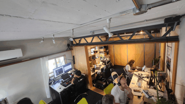
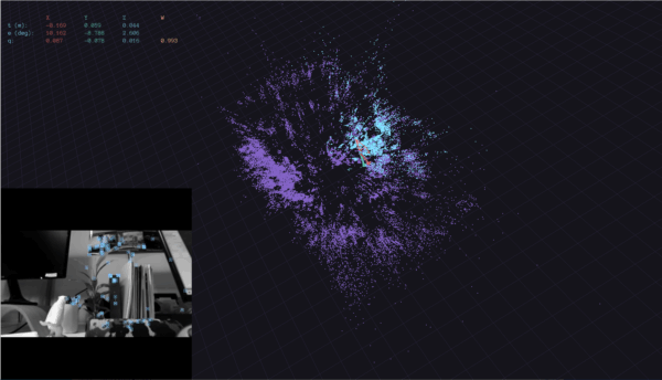
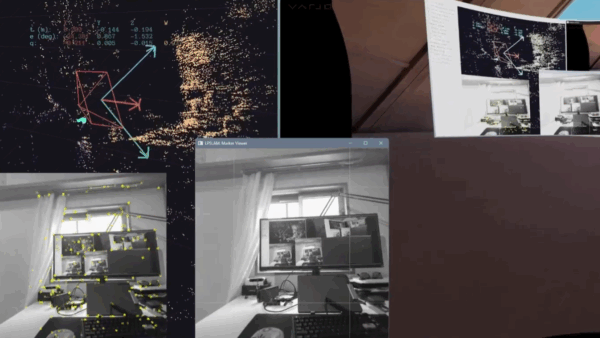
In the current state of our developments we ran tests in our laboratory. The images below show a photo of the environment next to how this environment translates into an LPSLAM map.

Tracking Across Larger Areas

A walk through the office based on a pre-built map yields good results. The fusion in this experiment is our regular IMU-optical fusion and therefore doesn’t support translation information with integrating accelerometer data. This leads to short interruptions of position tracking in certain areas where feature points aren’t found. We at least partially solve this problem with the full fusion shown in the next paragraph.

What is Full Fusion?

Traditional tracking systems rely either on Visual SLAM or IMU (Inertial Measurement Unit) data, often with one compensating for the other. Our Full Fusion approach goes beyond orientation fusion and integrates both IMU and SLAM data to estimate not just orientation but also position. This combination provides smoother, more stable tracking even in complex, dynamic environments where traditional methods tend to struggle.

By fusing IMU velocity estimates with visual SLAM pose data through a through a specialized filter algorithm, our system handles rapid movements gracefully and removes jitter seen in pure SLAM-only tracking. The IMU handles fast short-term movements while SLAM ensures long-term positional stability. Our latest releases even support alignment using fiducial markers, allowing the virtual scene to anchor precisely to the real world. The video below shows the SLAM in conjunction with the Full Fusion.

Real-World Testing and Iteration

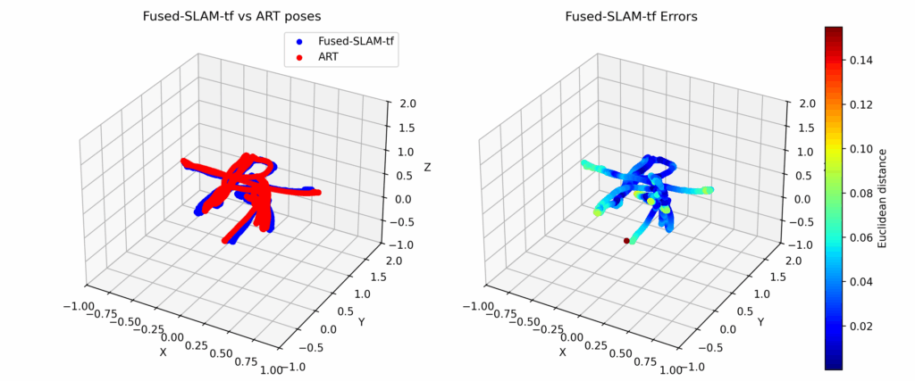
We’ve extensively tested this system in both lab conditions and challenging real-world environments. Our recent experiments demonstrated excellent results. By integrating our LPMS IMU sensor and running our software pipeline (LPSLAM and FusionHub), we achieved room-scale tracking with sub-centimeter accuracy and rotation errors as low as 0.45 degrees.

In order to evaluate the performance of the overall solution we compared the output from FusionHub with pose data recorded by an ART Smarttrack 3 tracking system. The accuracy of an ART tracking system is in the sub-mm range and therefore is sufficienty accurate to characterize the performance of our SLAM. The result of one of several measurement runs is shown in the image below. Note that both systems were alignment and timestamp synchronized to correctly compare poses.

Developer-Friendly and Cross-Platform

The LP-Research SLAM and FusionHub stack is designed for flexibility. Components can run on the PC and stream results to an HMD wirelessly, enabling rapid development and iteration. The system supports OpenXR-compatible headsets and has been tested with Meta Quest 3, Varjo XR-3, and more. Developers can also log and replay sessions for detailed tuning and offline debugging.

Looking Ahead

Our roadmap includes support for optical flow integration to improve SLAM stability further, expanded hardware compatibility, and refined UI tools for better calibration and monitoring. We’re also continuing our efforts to improve automated calibration and simplify the configuration process.

This is just the beginning. If you’re building advanced AR/VR systems and need precise, low-latency tracking that works in the real world, LP-Research’s Full Fusion system is ready to support your journey.

To learn more or get involved in our beta program, reach out to us.

LPVR-DUO in an Airborne Helicopter

In-Flight VR

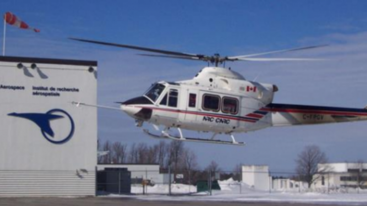
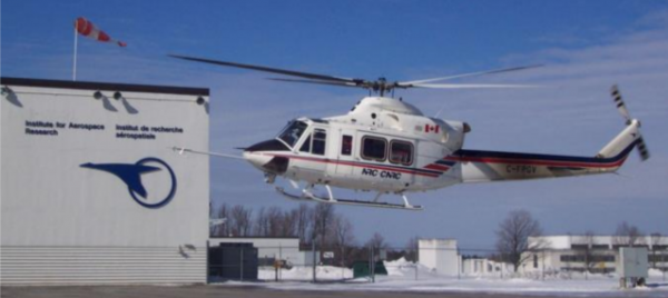
Imagine soaring through the skies as a pilot, testing the limits of a helicopter’s capabilities while feeling the rush of wind and turbulence. Now imagine that you don’t see the real world outside and the safe landing pad that your helicopter is approaching but a virtual reality (VR) scene where you are homing in on a ship in high seas. The National Research Council Canada (NRC) and Defence Research and Development Canada (DRDC) have brought this experience to life with their groundbreaking Integrated Reality In-Flight Simulation (IRIS).

IRIS is not your ordinary simulator; for one, it’s not sitting on a hexapod, it’s airborne. It’s a variable-stability helicopter based on the Bell 412 that can behave like other aircraft and can simulate varying weather conditions; combine that with a VR environment and you have a tool that allows safely training operations in the most adverse conditions. In particular it is used for Ship Helicopter Operating Limitations (SHOL) testing.

Mission-Critical Application with LPVR-DUO

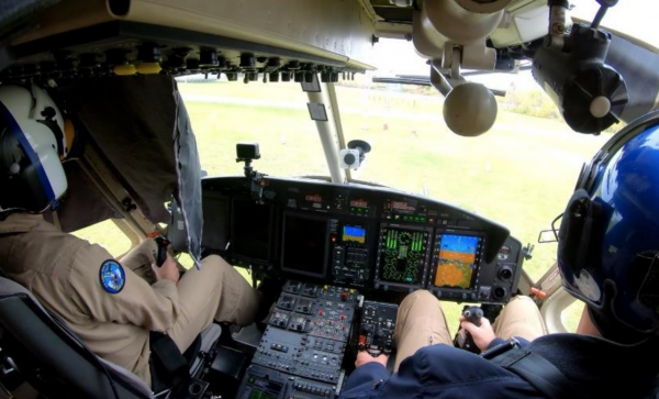
The LPVR-DUO system is what makes VR possible on this constantly moving platform. This cutting-edge AR/VR tracking system seamlessly merges the inertial measurements taken by the headset with the helicopter’s motion data and a camera system mounted inside the cabin to provide the correct visuals to the pilot. The challenges of using cameras to track the VR headset inside the tight environment of the helicopter while lighting conditions are ever-changing are overcome by using an ART SmartTrack 3 system. This system follows an arrangement of reflective markers attached to the pilot’s helmet. The VR headset is attached to the helmet in such a way that the pilot can wear it as if it were a pair of night vision goggles. Put together, this allows displaying a virtual world to the pilot, even in the most extreme maneuvers.

To ensure an authentic experience, the IRIS system incorporates real-time turbulence models, meticulously crafted from wind tunnel trials. These turbulence effects are seamlessly integrated into the aircraft’s motion and into the VR scene, providing pilots with precise proprioceptive and vestibular cues. It’s a symphony of technology and innovation in the world of aviation testing.

In-Cockpit Implementation

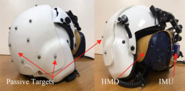
The optical tracking system relies on highly reflective marker targets on the helmet to track movement in three dimensions. Initially, only five markers were installed, strategically placed for optimal tracking. But the pursuit of perfection led NRC to create custom 3D-printed low-reflectivity helmet molds, allowing them to mount a dozen small passive markers. This significantly improved tracking reliability in various lighting conditions and allowed for a wider range of head movement.

Recently, NRC put this remarkable concept to the test with actual flight trials. The response from pilots was nothing short of exhilarating. They found the system required minimal adaptation, exhibited no noticeable lag, and, perhaps most impressively, didn’t induce any motion sickness. Even the turbulence effects felt incredibly realistic. Surprisingly, the typical VR drawbacks, such as resolution and field of view limitations, had minimal impact, especially during close-in shipboard operations. It’s safe to say that IRIS has set a new standard for effective and immersive aviation testing.

Publication of Results

The NRC team presented their results at the Vertical Flight Society’s 79th Annual Form in two papers [1] and [2] and they also have a blog post on their site.

NOTE: Image contents courtesy of Aerospace Research Centre, National Research Council of Canada (NRC) – Ottawa, ON, Canada

Exploring Affective Computing Concepts

Introduction

Emotional computing isn’t a new field of research. For decades computer scientists have worked on modelling, measuring and actuating human emotion. The goal of doing this accurately and predictively has so far been elusive.

pngwing.com

In the past years we have worked with the company Qualcomm to create intellectual property related to this topic, in the context of health care and the automotive space. Even though this project is pretty off-topic from our ususal focus areas it is an interesting sidetrack that I think is worth posting about.

Affective Computing Concepts

As part of the program we have worked on various ideas ranging from relatively simple sensory devices to complete affective control systems to control the emotional state of a user. Two examples of these approaches to emotional computing are shown below.

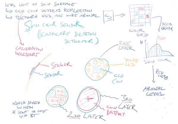
The Skin Color Sensor measures the color of the facial complexion of a user, with the goal of estimating aspects of the emotional state of the person from this data. The sensor is to have the shape of a small, unobtrusive patch to be attached to a spot on the forehead of the user.

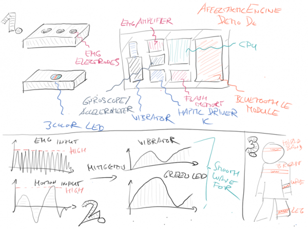
Another affective computing concept we have worked on is the Affectactic Engine. A little device that measures the emotional state of a user via an electromyography sensor and accelerometer. Simply speaking we are imagining that high muscle tension and certain motion patterns correspond to a stressed emotional state of the user or represent a “twitch” a user might have.

The user is to be reminded of entering this “stressed” emotional state by vibrations emitted from the device. The device is to be attached to the body of the user by a wrist band, with the goal of reminding the user of certain subconscious stress states.

Patents

In the course of this collaboration we created several groundbreaking patents in the area of affective computing:

How to Use LPMS IMUs with LabView

Introduction

LabView by National Instruments (NI) is one of the most popular multi-purpose solutions for measurement and data acquisition tasks. A wide range of hardware components can be connected to a central control application running on a PC. This application contains a full graphical programming language that allows the creation of so called virtual instruments (VI).

Data can be acquired inside a LabView application via a variety of communication interfaces, such as Bluetooth, serial port etc. A LabView driver that can communicate with our LPMS units has been a frequently requested feature from our customers for some time, so that we decided to create this short example to give a general guideline.

A Simple Example

The example shown here specifically works with LPMS-B2, but it is easily customizable to work with other sensors in our product line-up. In order to communicate with LPMS-B2 we use LabView’s built-in Bluetooth access modules. We then parse the incoming data stream to display the measured values.

The source code repository for this example is here.

Figure 1 – Overview of a minimal virtual instrument (VI) to acquire data from LPMS-B2

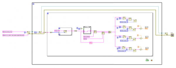
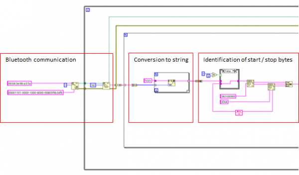
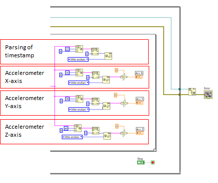
Fig. 1 shows an overview of the example design to acquire the accelerometer X, Y, Z axes of the IMU and displays them on a simple front panel. Fig. 2 & 3 below show the virtual instrument in more detail. After reading out the raw data stream from the Bluetooth interface, this data stream is converted into a string. The string is then evaluated to find the start and stop character sequence. The actual data is finally extracted depending on its position in the data packet.

Figure 2 – Bluetooth access and initial data parsing

Figure 3 – Extraction of timestamp, accelerometer X, Y, Z values

Notes

Please note that the example requires manually entering the Bluetooth ID of the LPMS-B2 in use. The configuration of the data parsing is static. Therefore the output data of the sensor needs to be configured and saved to sensor flash memory in the LPMS-Control application. For reference please check the LPMS manual.

An initial version of this virtual instrument was kindly provided to us by Dr. Patrick Esser, head of the Movement Science Group at Oxford Brooks University, UK.

1 2 3