New Features in LPVR Version 4.8
Introduction
Our LPVR series is the primary solution on the market for users who want to expand the scope of their virtual reality or mixed reality headsets by using external tracking systems such as ART, OptiTrack or Vicon. Use cases are varied and range from entertainment (location based VR) and engineering use cases (ergonomic studies in AR) to helicopters and virtual cars which are actually driving on Japan’s public roads. At LP-Research, we have continuously developed the LPVR series of solutions over the past years. We have expanded its scope, added support for new headsets, and included new functions.
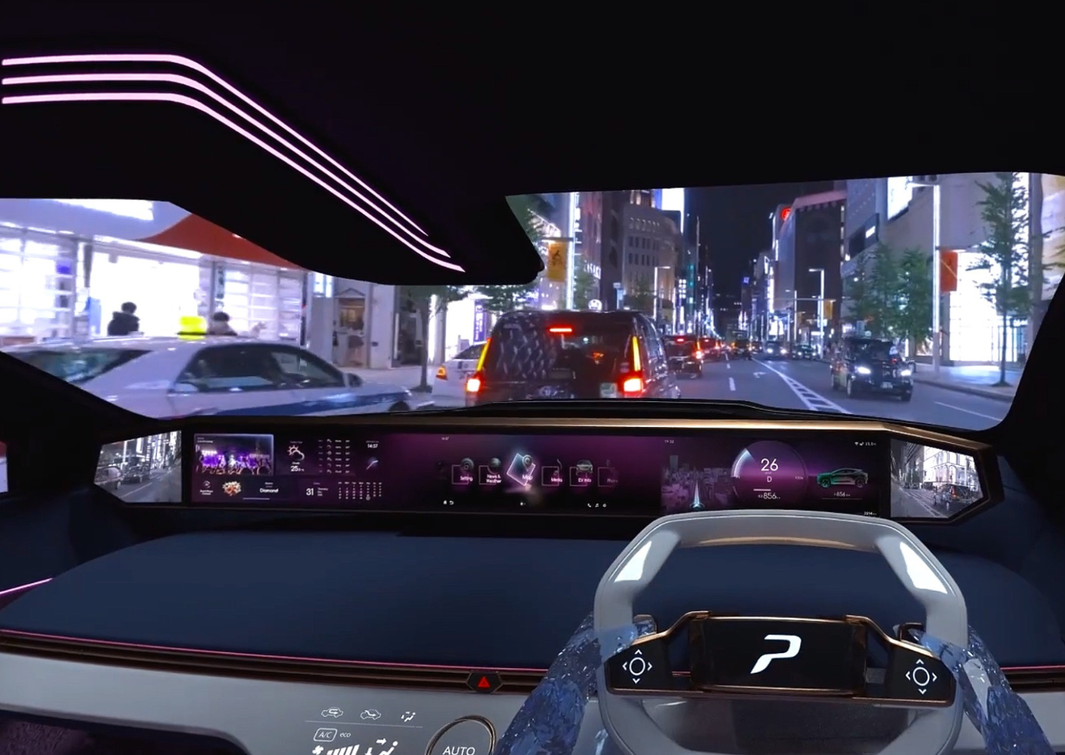
The image below shows an LPVR installation based on design content created by automotive prototyping company Phiaro Inc. in Tokyo, Japan.
The latest release is version 4.8.0, which we released in June of 2023. As usual, it comes in two flavors:
- LPVR-CAD which supports stationary use-cases, and
- LPVR-DUO which is our variant for moving platforms, be they cars or simulators.
We support all the major tethered headsets (SteamVR headsets, Pimax, Varjo). We also support Meta Quest series headsets and the Vive Focus 3 with our LPVR-Air series of products. If you have a current support contract, you are eligible for an update.
A Brief Overview of LPVR-CAD and LPVR-DUO
It’s maybe best to summarize some of the capabilites that our products add to the various commercial headsets. For more details, feel free to visit the product pages for LPVR-CAD and LPVR-DUO, respectively:
- Cover arbitrary large areas and have VR scenes taking place in them
- Have an arbitrary number of users interact in such a space
- Do VR/AR inside a car or any other moving platform
- Track your user to sub-millimeter precision together with any number of props with no perceivable latency
- Use SteamVR controllers without the Lighthouses
We can do this because our proprietary sensor fusion algorithms allow us to combine the measurements of high-precision motion tracking camera systems with the measurements of the headset’s Inertial Measurement Unit (IMU). For the case of a moving platform, we can additionally incorporate data from an IMU installed on the platform to provide for a responsive, accurate performance also in those circumstances.
New Features
For a short overview of the changes in each version, please refer to our Release Notes. Here we will give some highlights and dig into some details. LPVR 4.8.0 is the result of continuous development in the half year or so since our previous releases.
New GUI Organization and Visual LPVR-DUO Configuration Interface
The most obvious change to users will be the reorganized GUI which streamlines the setup, completely doing away with the need to enter any JSON codes, while coming on a more cleanly organized surface. Especially for our LPVR-DUO users this means a vast simplification of the system. We have maintained the old configuration interface as an option to guarantee compatibility with existing workflows, but we don’t think that users will have to resort to it. Please let us know if your experience is different. If your headset tracking body is already calibrated, you should now be able to setup LPVR-DUO with some five mouse clicks.
When you load up the configuration, it will look something like this. Note that you no longer are led to a JSON editor where you manually have to enter the configuration. Instead you are greeted by a friendly, informative GUI.
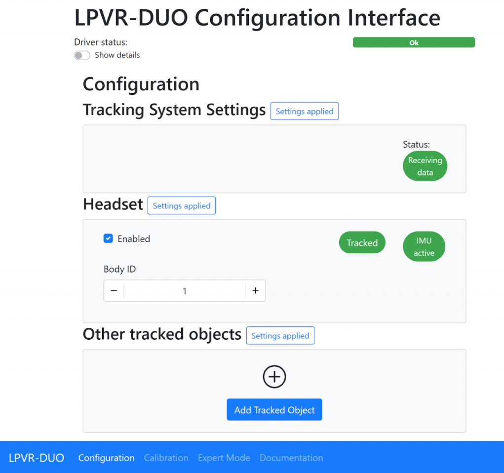
At the bottom of the page, you will see links to the Documentation, a Calibration screen, and an Expert Mode, basically the old JSON editor. The Calibration screen is used for the setup of the Platform IMU and simplifies it down to a few mouse clicks in the usual case. No more looking for some quaternion values in log files! Please check out the corresponding documentation.
Varjo Headset Eye Point Adjustments
Together with Varjo and with cooperation of several of our customers we were able to identify and correct some imprecisions in the handling of the headset’s position. These would show up as small coordinate mismatches between the optical tracking coordinates and the coordinates reported to VRED or Unity etc. Additionally, this would lead to some unnatural motion of AR overlays, especially when turning the head.
Optimal performance requires updating both Varjo Base to at least version 3.10 and LPVR to at least version 4.8.0. Updating Varjo Base fixes the underlying issue, updating LPVR corrects the interfacing. If you cannot update Varjo Base, you can still update LPVR-CAD-Varjo to version 4.8.0 and enable a workaround. To do so, please open the Varjo Base configuration GUI on the System tab and then add patchPositionBug=true in the field labeled Additional Settings followed by clicking the “Submit” button. Note while this works around the issue in Varjo Base before version 3.10, it is not recommended to use this option with the updated versions of Varjo Base.
Varjo Configuration Refinements
Different environments call for different setups. Some of our users use administrator accounts, others have multiple users but want them to use the same configuration. We have updated the way we organize on-disc storage of the configuration to address these possibilities. In particular you can now establish a system-wide configuration default, and you can override it per-user. In the case of LPVR-CAD, additionally, the configuration is entered inside Varjo Base by default, but to allow users greater flexibility, it has always been possible to use our web interface or files on disk to perform the configuration. While these are not the preferred choice, it was previously not possible to see from Varjo Base whether the on-disk configuration is in use. We have added a prominent status information that points to the configuration, as in the screen shot below. In the case of LPVR-DUO the configuration is always loaded from disk as the added flexibility of our configuration page is required, but in LPVR-CAD the user will have to opt in. We describe the process briefly below.
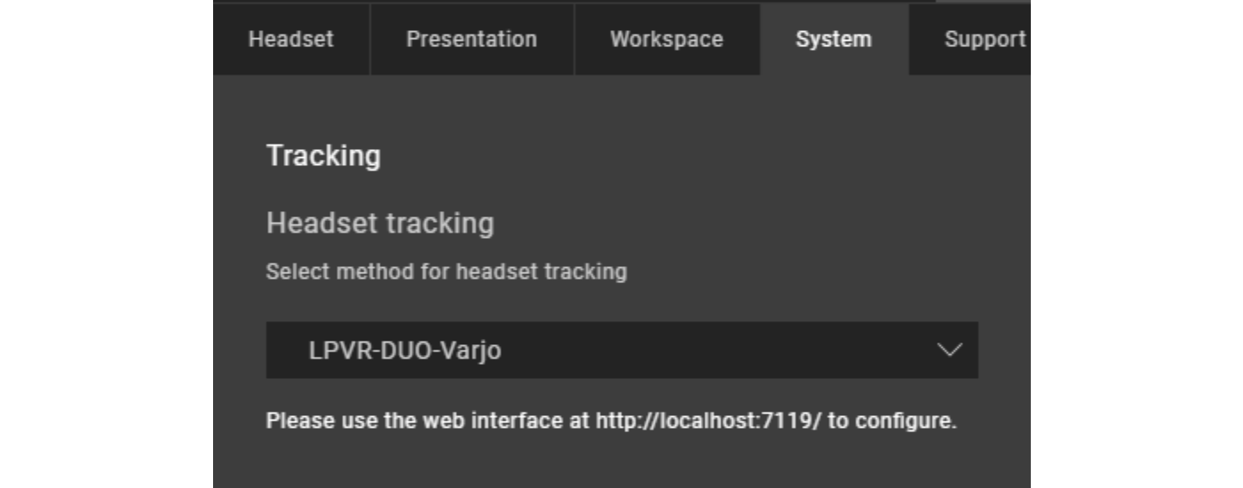
The user can prepare a global, system-wide default configuration in %ProgramData%/Varjo/VarjoTracking/Plugins/LP-Research/LPVR-CAD-Varjo/configuration/settings.json. Changes on the configuration page will not change this configuration, but will instead be written to the per-user configuration %LocalAppData%/LP-Research/LPVR-CAD-Varjo/settings.json. If either file is present, the configuration inside Varjo Base will be ignored and the user can use their web browser to configure LPVR-CAD. In this way, an administrator can prepare a configuration that works with the setup, and any user can customize it to their needs. For LPVR-DUO, there is no configuration interface inside Varjo Base, instead the user will always point their web browser to http://localhost:7119. Here, a system-wide default configuration can be placed in %ProgramData%/Varjo/VarjoTracking/Plugins/LP-Research/LPVR-DUO-Varjo/configuration/settings.json, and a per-user override can sit in %LocalAppData%/LP-Research/LPVR-DUO-Varjo/settings.json. The web interface will always update this per-user file.
LPVR-DUO Demonstration
In order to familiarize you with the neighborhood of our office and, more importantly, to show what can be done with LPVR-DUO, here is an in-car mixed reality demonstration. The video screens on the glove box may look almost real but they are an overlay imposed on the see-through camera image of a Varjo XR-3 using an out-of-the-box LPVR-DUO set. Notice how the screens firmly remain in place during turns of the user’s head as well as turns of the car itself, even when diving into some of the steeper roads of the Motoazabu area in central Tokyo.