Blog

LPNAV-VAC – Cost-Efficient Navigation System for AGVs

Introduction

We’re proud to announce a breakthrough result in the development of our LPNAV low-cost navigation system for small-sized automatic guided vehicles (AGV).

One focus area of LPNAV are vacuum cleaning robots that require spatial understanding of their environment to calculate an optimum cleaning strategy. As vacuum cleaning robots are mainly consumer devices, solutions for this market need to be cost-efficient, while maintaining state-of-the-art performance.
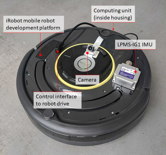
Figure 1 – The LPNAV-VAC development kit contains a robot platform, a dedicated computing unit, an IMU sensor and a camera

Development Platform

LPNAV-VAC combines three different data sources in order to calculate a robot’s position inside a room: an inertial measurement unit, data from the robot’s wheel encoders and video images from a camera installed on the robot (Figure 1). A central computing unit combines the information from these data sources to simultaneously create a map of the surroundings of the robot and calculate the position of the robot inside the room.

It is essential that sensor fusion algorithm is able to dynamically update the map it is constructing. As new sensor information arrives the map is continuously adapted to reflect an optimized view the robot’s environment.

While this principle of simultaneous localization and mapping (SLAM) is an established method for some robot navigation systems, these solutions tend to rely on laser scanners (LIDAR) or vision-only reconstruction. The combination of all available data sources in the robot allows LPNAV-VAC to create high definition maps of the environment while using low-cost, off-the-shelf components.

video

First Demonstration

In the demonstration video above my colleague and main developer of LPNAV-VAC is steering our AGV platform through the ground floor of our Tokyo office. While the right side of the screen shows the view from the robot camera and detected visual features, the right side shows the path of the robot through the environment. As the robot progresses through the room a 3D map is created and continuously updated.

Please note that the robot doesn’t lose tracking during turns, while driving over small steps in the room or with changing environment lighting. Also Thomas moving around in front of the camera doesn’t disturb the LPNAV algorithm.

Using this map and the robot’s position information a path planning algorithm can find an optimum path for the robot to efficiently clean the room.
See-through Display First Look – LPVIZ (Part 3)

Virtual Dashboard Demonstration

This is a follow-up post to the introduction of our in-vehicle AR head mounted display LPVIZ part 1 and part 2.

To test LPVIZ we created a simple demo scenario of an automotive virtual dashboard. We created a Unity scene with graphic elements commonly found on a vehicle dashboard. We animated these elements to make the scene look more realistic.

This setup is meant for static testing at our shop. For further experiments inside a moving vehicle we are planning to connect the animated elements directly to car data (speed etc.) communicated over the CAN bus.

The virtual dashboard is only a very simple example to show the basic functionality of LPVIZ. As described in a previous post, many a lot more sophisticated applications can be implemented.

video

The video above was taken through the right eye optical waveguide display of LPVIZ. We took this photo with a regular smartphone camera and therefore it is not very high quality. Nevertheless, it confirms that the display is working and correctly shows the virtual dashboard.

The user is looking at the object straight ahead. In case the user rotates his head or changes position, his view of the object will change perspectively. An important point to mention is the high luminosity of the display. We took this photo with the interior lighting in our shop turned on normally, and without any additional shade in front of the display.

How to Use LPMS IMUs with LabView

Introduction

LabView by National Instruments (NI) is one of the most popular multi-purpose solutions for measurement and data acquisition tasks. A wide range of hardware components can be connected to a central control application running on a PC. This application contains a full graphical programming language that allows the creation of so called virtual instruments (VI).

Data can be acquired inside a LabView application via a variety of communication interfaces, such as Bluetooth, serial port etc. A LabView driver that can communicate with our LPMS units has been a frequently requested feature from our customers for some time, so that we decided to create this short example to give a general guideline.

A Simple Example

The example shown here specifically works with LPMS-B2, but it is easily customizable to work with other sensors in our product line-up. In order to communicate with LPMS-B2 we use LabView’s built-in Bluetooth access modules. We then parse the incoming data stream to display the measured values.

The source code repository for this example is here.

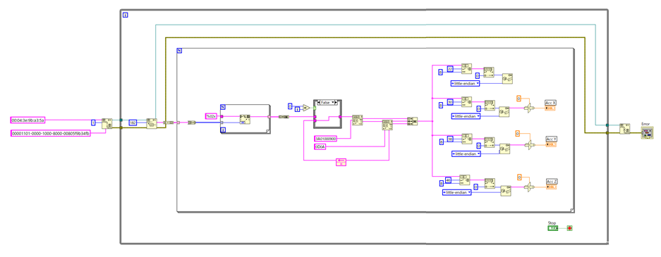
Figure 1 – Overview of a minimal virtual instrument (VI) to acquire data from LPMS-B2

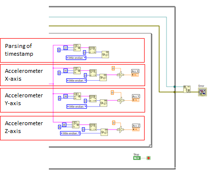
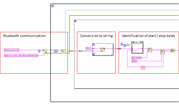
Fig. 1 shows an overview of the example design to acquire the accelerometer X, Y, Z axes of the IMU and displays them on a simple front panel. Fig. 2 & 3 below show the virtual instrument in more detail. After reading out the raw data stream from the Bluetooth interface, this data stream is converted into a string. The string is then evaluated to find the start and stop character sequence. The actual data is finally extracted depending on its position in the data packet.

Figure 2 – Bluetooth access and initial data parsing

Figure 3 – Extraction of timestamp, accelerometer X, Y, Z values

Notes

Please note that the example requires manually entering the Bluetooth ID of the LPMS-B2 in use. The configuration of the data parsing is static. Therefore the output data of the sensor needs to be configured and saved to sensor flash memory in the LPMS-Control application. For reference please check the LPMS manual.

An initial version of this virtual instrument was kindly provided to us by Dr. Patrick Esser, head of the Movement Science Group at Oxford Brooks University, UK.

Your cart

Subtotal$0.00
Tax + shipping calculated at checkout.

Page history

Asset library