LPNAV-VAC – Cost-Efficient Navigation System for AGVs
Introduction
We’re proud to announce a breakthrough result in the development of our LPNAV low-cost navigation system for small-sized automatic guided vehicles (AGV).
One focus area of LPNAV are vacuum cleaning robots that require spatial understanding of their environment to calculate an optimum cleaning strategy. As vacuum cleaning robots are mainly consumer devices, solutions for this market need to be cost-efficient, while maintaining state-of-the-art performance.
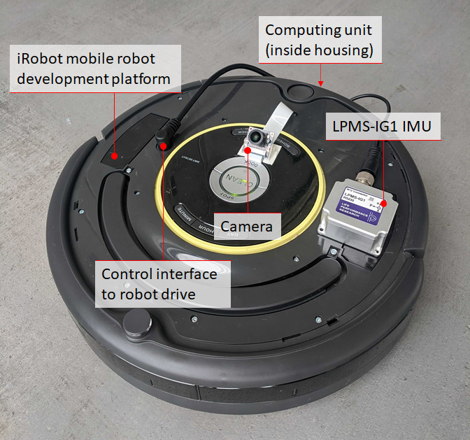
Figure 1 – The LPNAV-VAC development kit contains a robot platform, a dedicated computing unit, an IMU sensor and a camera
Development Platform
LPNAV-VAC combines three different data sources in order to calculate a robot’s position inside a room: an inertial measurement unit, data from the robot’s wheel encoders and video images from a camera installed on the robot (Figure 1). A central computing unit combines the information from these data sources to simultaneously create a map of the surroundings of the robot and calculate the position of the robot inside the room.
It is essential that sensor fusion algorithm is able to dynamically update the map it is constructing. As new sensor information arrives the map is continuously adapted to reflect an optimized view the robot’s environment.
While this principle of simultaneous localization and mapping (SLAM) is an established method for some robot navigation systems, these solutions tend to rely on laser scanners (LIDAR) or vision-only reconstruction. The combination of all available data sources in the robot allows LPNAV-VAC to create high definition maps of the environment while using low-cost, off-the-shelf components.
First Demonstration
In the demonstration video above my colleague and main developer of LPNAV-VAC is steering our AGV platform through the ground floor of our Tokyo office. While the right side of the screen shows the view from the robot camera and detected visual features, the right side shows the path of the robot through the environment. As the robot progresses through the room a 3D map is created and continuously updated.
Please note that the robot doesn’t lose tracking during turns, while driving over small steps in the room or with changing environment lighting. Also Thomas moving around in front of the camera doesn’t disturb the LPNAV algorithm.
Using this map and the robot’s position information a path planning algorithm can find an optimum path for the robot to efficiently clean the room.